
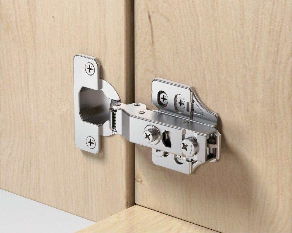

Technical support, from planning to final alignment
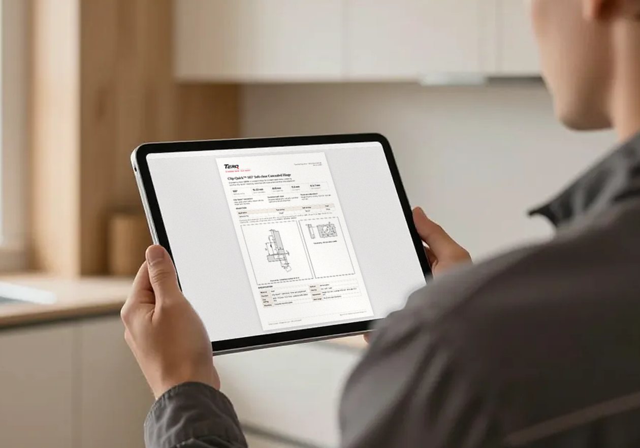
Data sheets, installation drawings and engineering references for every Terq hinge, prepared for cabinet designers, production engineers and installers.
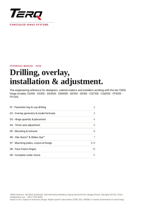
Documents for specification and installation
All documents are issued in English, version 2026.1. Dimensions in mm; subject to technical change.
Catalogue & reference
Complete range and system documentation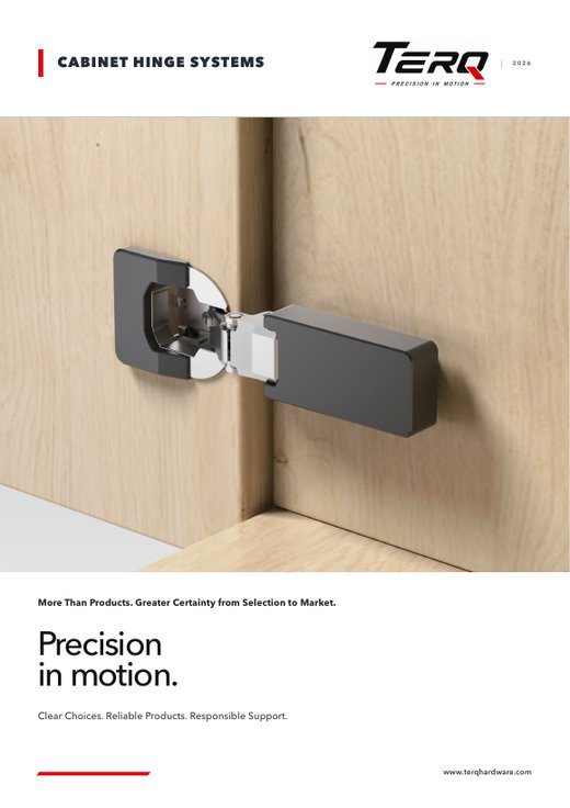
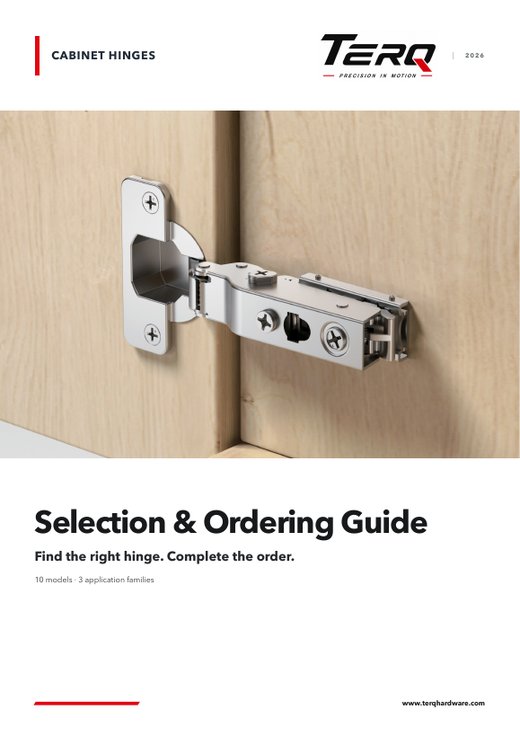
By model
Technical data sheet and installation drawings (2D · SVG · PDF)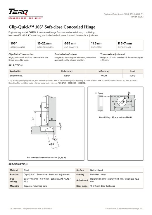
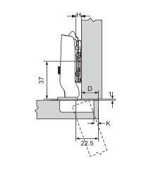
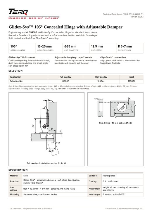
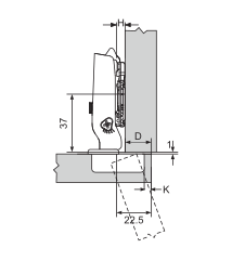
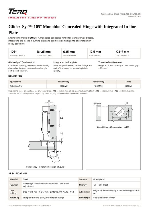
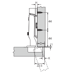
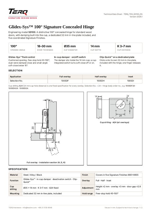
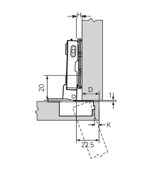
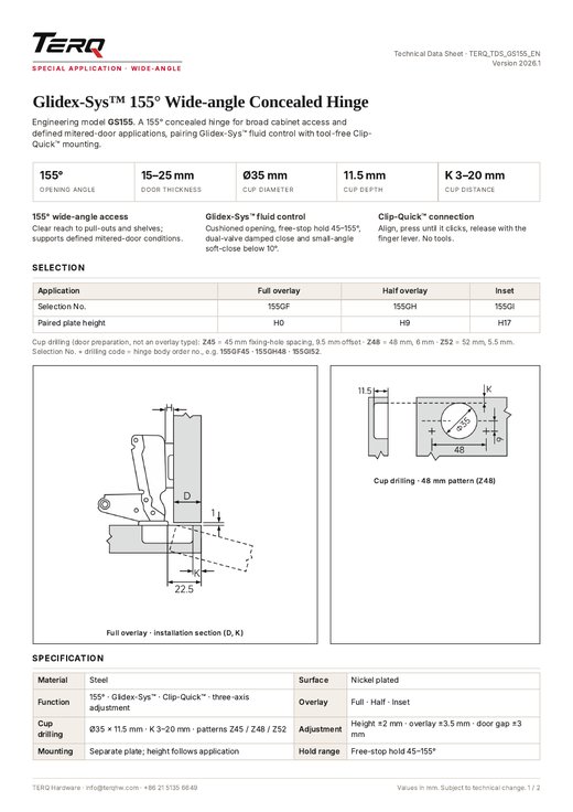
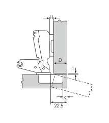
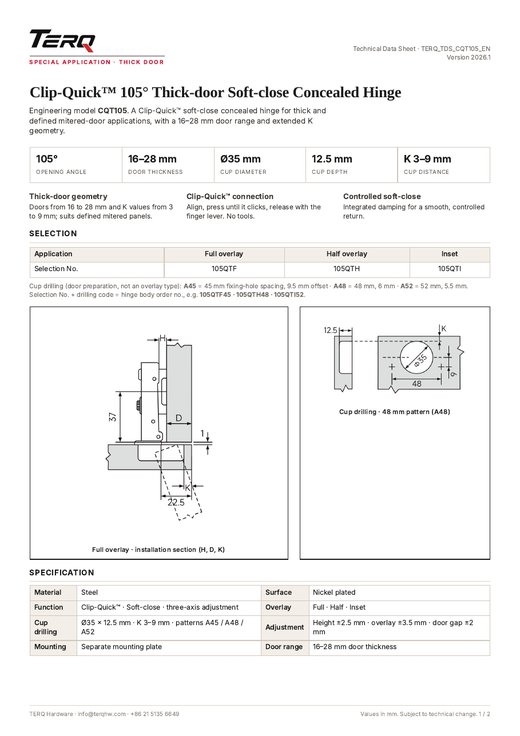
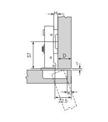
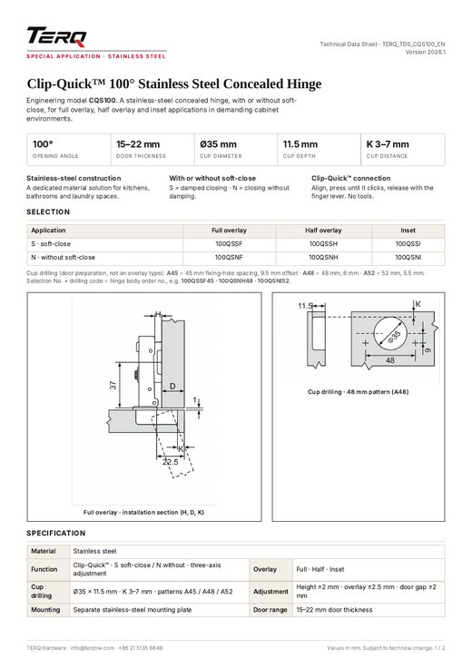
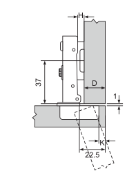
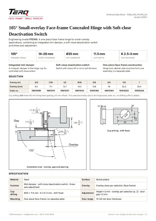
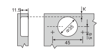
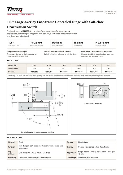
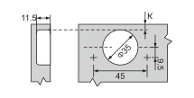
Plan, prepare, install and adjust
The shared geometry behind every Terq hinge, taken from the technical reference section of the catalogue. Model-specific values are given on each product page and data sheet.
Planning: hinge quantity & layout
Start from door height and maximum door weight, then verify the complete application. Place the top hinge center 60–100 mm from the door edge.
Hinge quantity by door height and weightReference for doors under 600 mm wideShow moreShow less
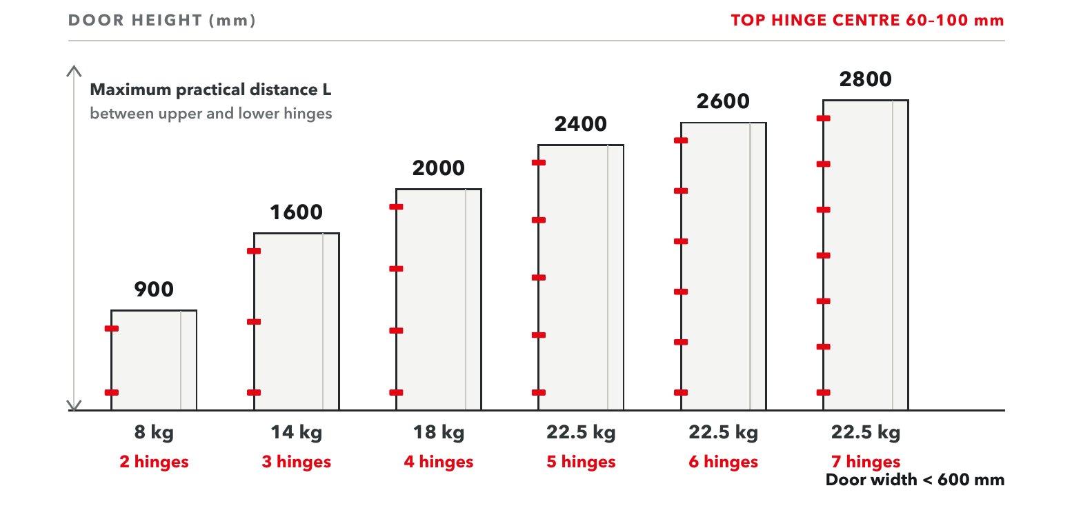
| Door height (mm) | Max. door weight | Hinges |
|---|---|---|
| up to 900 | 8 kg | 2 |
| up to 1600 | 14 kg | 3 |
| up to 2000 | 18 kg | 4 |
| up to 2400 | 22.5 kg | 5 |
| up to 2600 | 22.5 kg | 6 |
| up to 2800 | 22.5 kg | 7 |
Planning sequenceHeight and weight · distance L · exceptional conditionsShow moreShow less
If the door exceeds the stated range or the application is uncertain, verify the design or trial-assemble before production.
Drilling & clearance
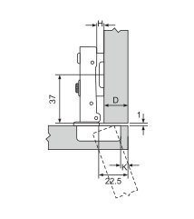
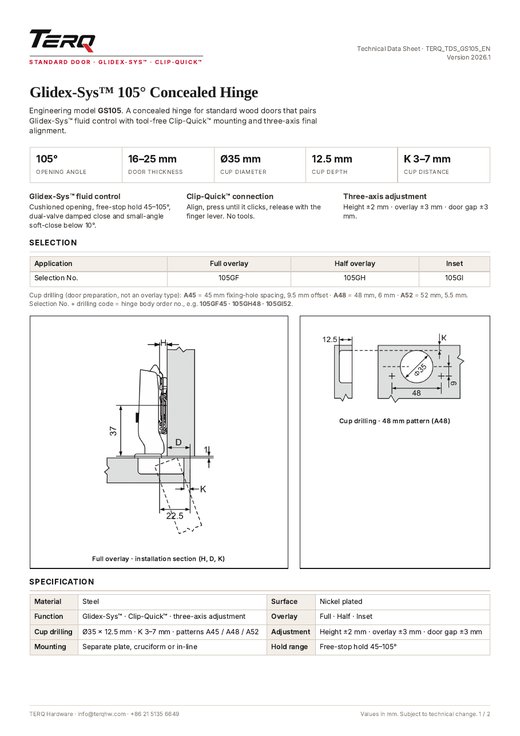
Confirm the machining pattern first, then read the application relationship with one shared parameter language. Shown for a Ø35 mm cup at 11.5 mm depth; cup depth varies by model (SD100: 14 mm).
Cup drilling patternsA45 · A48 · A52Show moreShow less
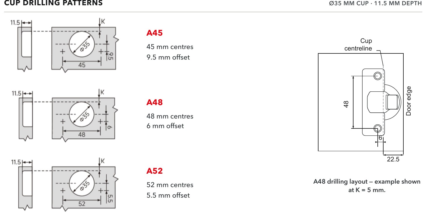
| Pattern | Fixing-hole centers | Offset |
|---|---|---|
| A45 | 45 mm | 9.5 mm |
| A48 | 48 mm | 6 mm |
| A52 | 52 mm | 5.5 mm |
Application relationship & parameter keyFull overlay · half overlay · insetShow moreShow less
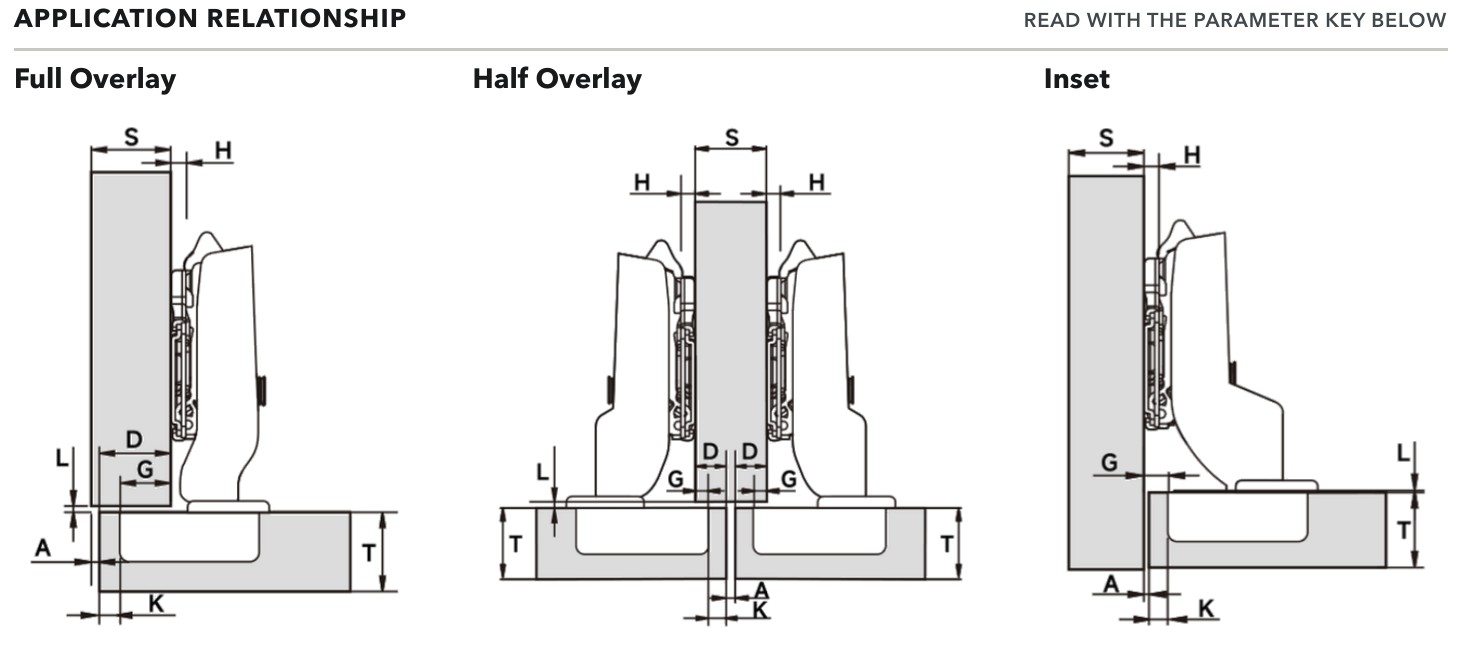
| S | Cabinet side-panel thickness | D | Required door overlay |
|---|---|---|---|
| T | Door thickness | K | Cup distance |
| A | Door reveal / application gap | L | Door-to-side-panel or internal clearance |
| H | Mounting-plate height | G | Hinge overlay position |
Confirm the model-specific drilling code, K range, formulas and clearance tables on the selected product page and data sheet.
Installation & adjustment
Follow only the sequence that matches the selected hinge structure, then make one controlled adjustment at a time and verify the finished door alignment.
Three-axis adjustmentOverlay · door gap · heightShow moreShow less
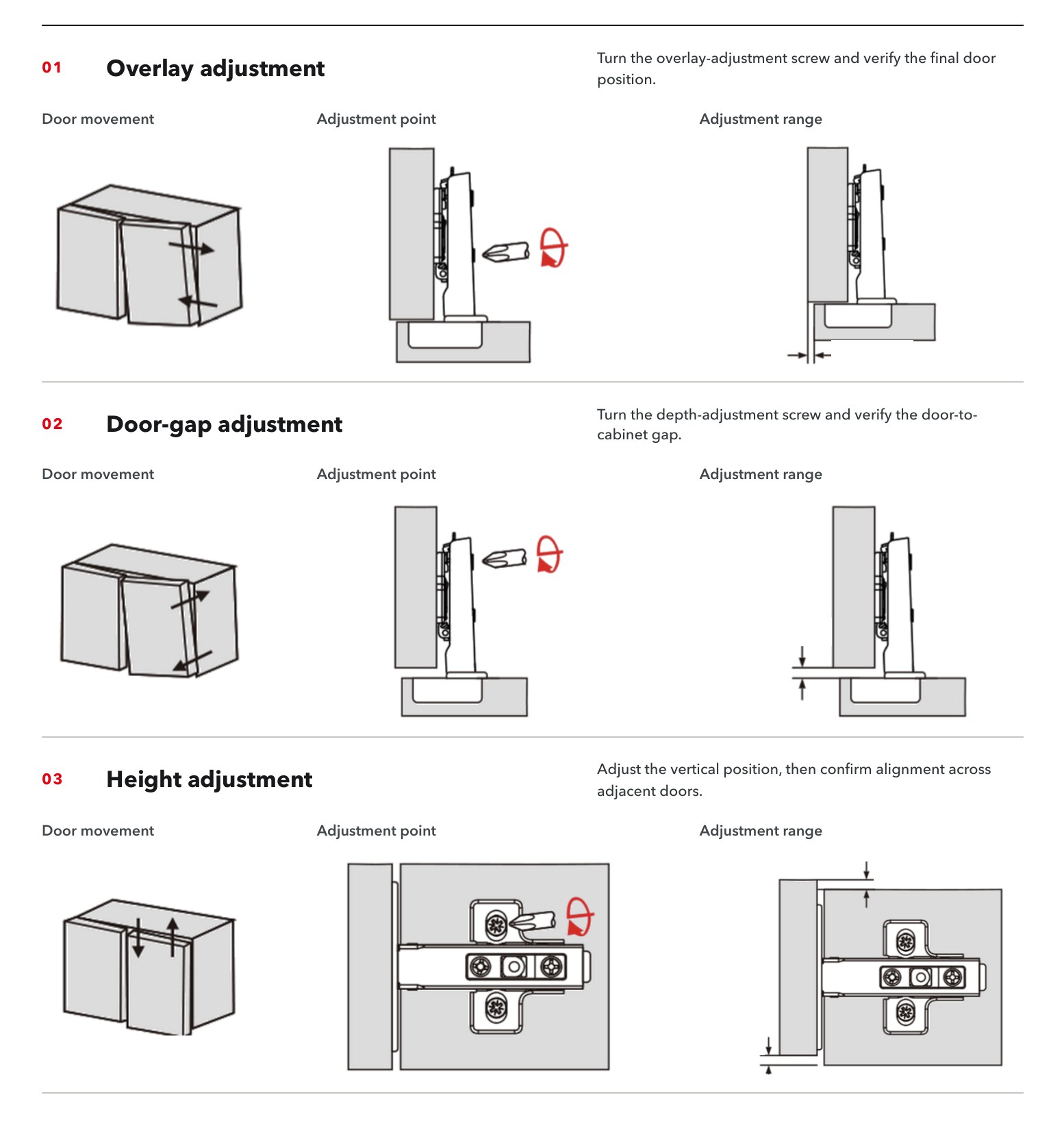
Adjustment values: see catalogue pp. 32–36. Product-specific ranges can differ; the selected product page and data sheet remain authoritative.
Installation & removal IClip-Quick™ · slide-on reference · monoblocShow moreShow less
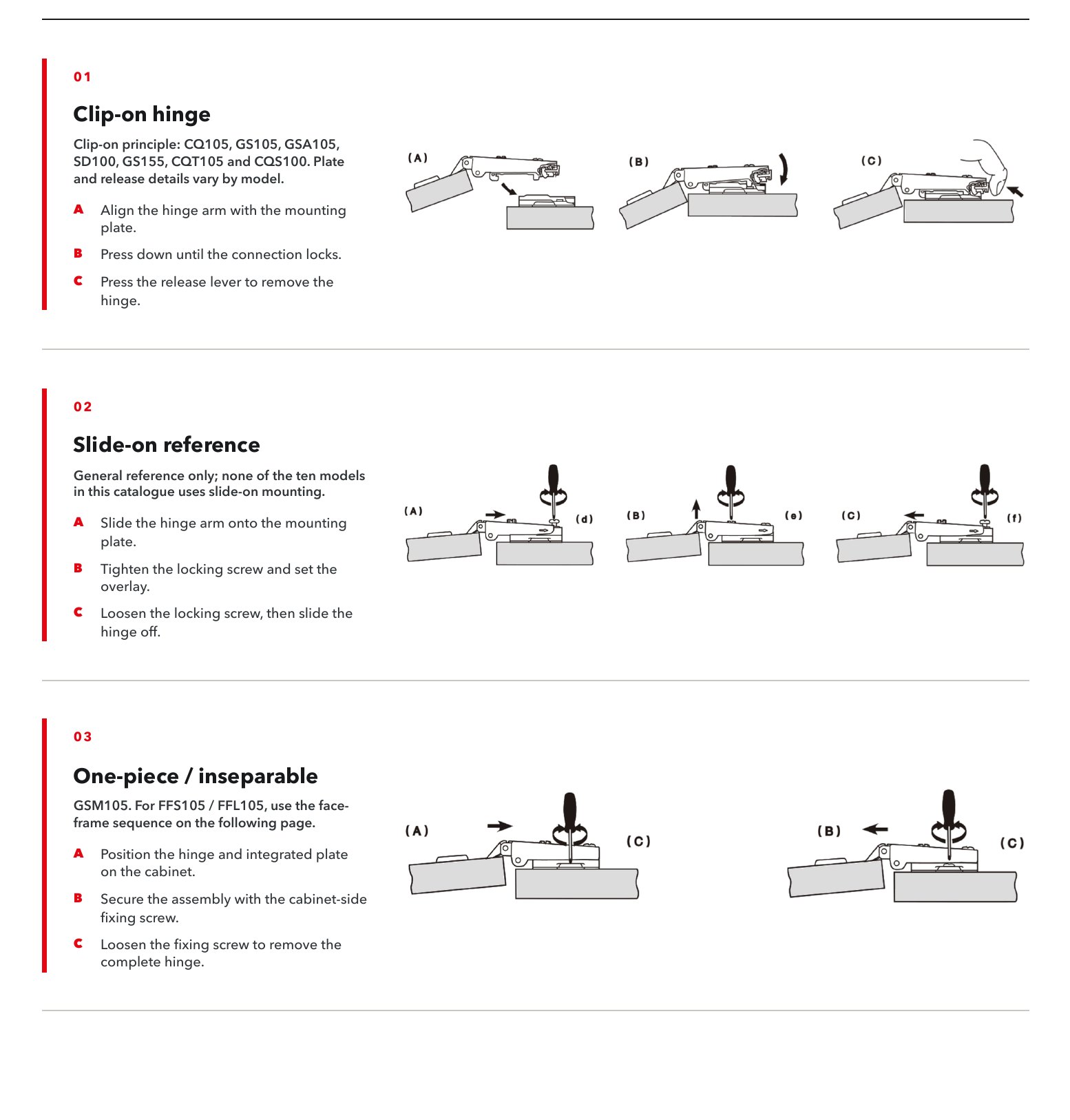
Installation & removal IIClip-Quick™ with 3D adjustment · face-frame · special-angleShow moreShow less
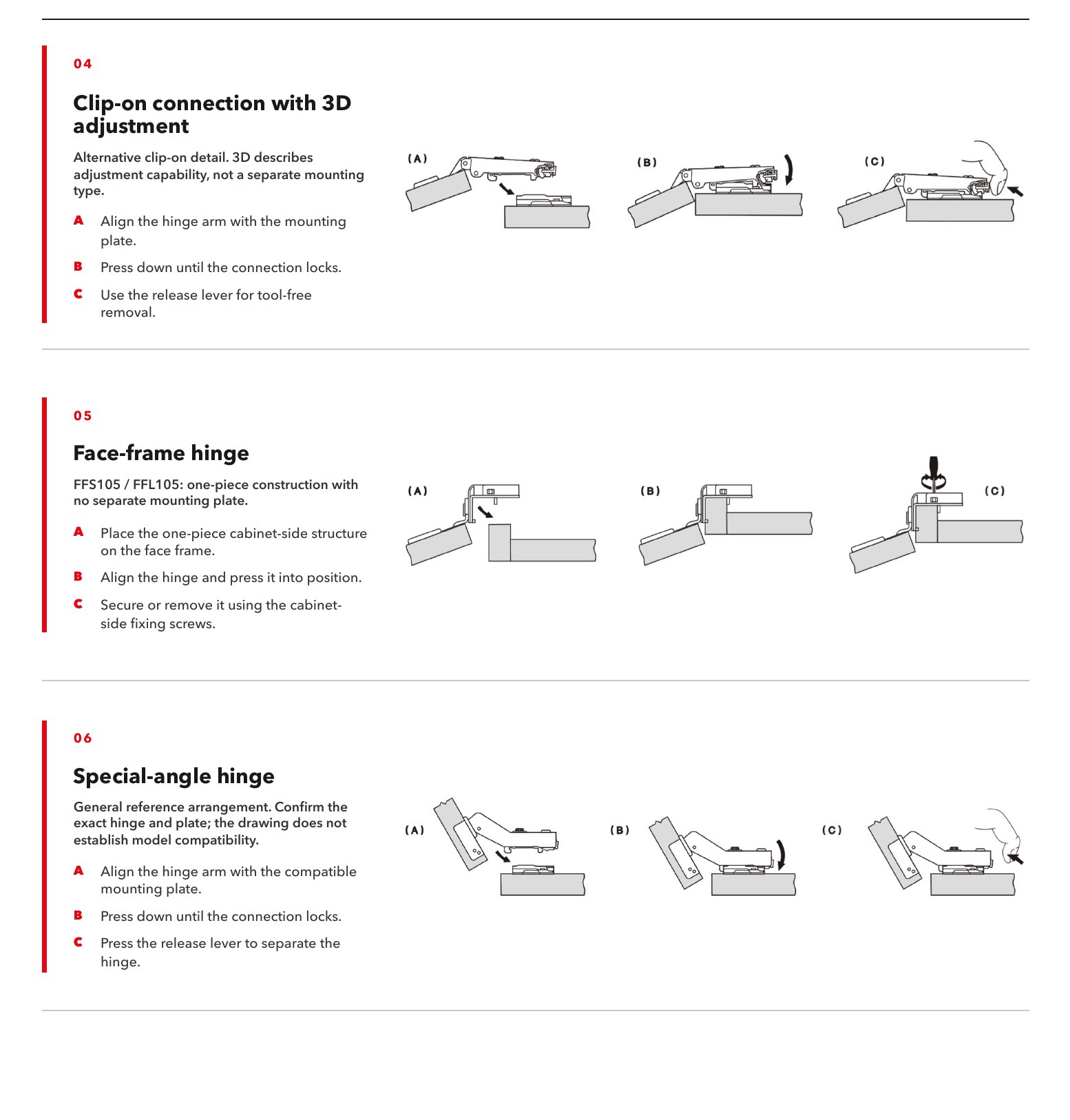
Confirm compatible mounting plates and required fixings before installation.
Frequently asked questions
Which cup drilling pattern should I use?Show moreShow less
Terq concealed hinges use a Ø35 mm cup. Most models have a cup depth of 11.5 mm or 12.5 mm; SD100, with its in-cup damper, uses 14 mm. Most models offer an A45, A48 or A52 fixing-hole pattern, which is part of the hinge body order number, for example 105QF45 or 105QH48. Some models use a dedicated or fixed pattern; confirm the cup depth and drilling codes for each model on its product page.
How many hinges does a door need?Show moreShow less
Use door height and maximum door weight as the starting point: two hinges up to 900 mm and 8 kg, rising to seven hinges at 2800 mm, for doors under 600 mm wide. Door material, handle position and dynamic use can change the required quantity.
How do I install and remove a Clip-Quick™ hinge?Show moreShow less
Align the hinge arm with the mounting plate and press down until the connection locks. Press the release lever to remove the hinge. No tools are required.
How is the door adjusted after installation?Show moreShow less
Each hinge adjusts on three axes: overlay, door gap and height. Make one controlled change at a time and verify the finished alignment. Adjustment values: see catalogue pp. 32–36 and the model data sheet.
Which mounting plate is compatible with my hinge?Show moreShow less
Compatible plates depend on the hinge structure and cabinet construction. The mounting plates page and each product page list the compatible plate and fixing for every model.
Do the face-frame hinges need a separate mounting plate?Show moreShow less
No. FFS105 and FFL105 are one-piece constructions that fix directly to the face frame, with no separate mounting plate.
What do the installation drawings contain?Show moreShow less
Each model has a ZIP of 2D drawings in SVG and PDF: application sections, cup drilling patterns and clearance references, prepared for cabinet design and door preparation.
Which document takes precedence?Show moreShow less
The product page and model data sheet are authoritative for model-specific values. The catalogue technical reference explains the shared geometry. All values are in mm and subject to technical change.
Discuss your application with our engineers
Share your door dimensions, cabinet construction and functional requirements. We will recommend the hinge, mounting plate and drilling configuration for your project.
- Hinge and plate selection
- Drilling and clearance review
- Installation and adjustment guidance
- Documentation for production